
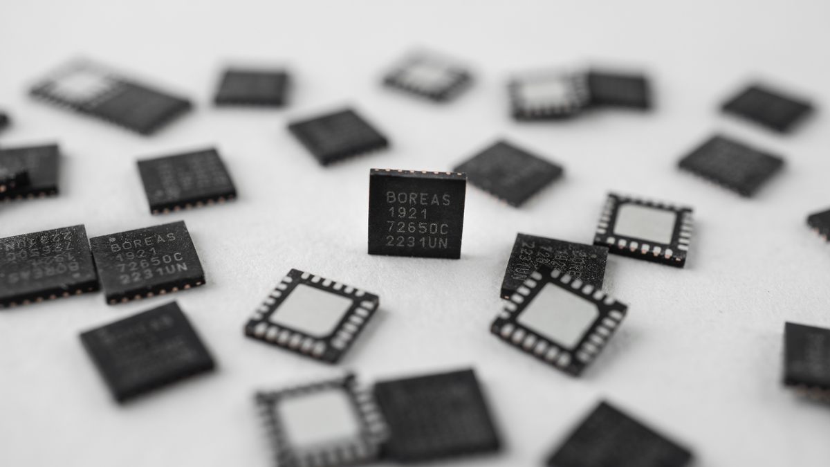
CapDrive is a high-voltage piezo driver architecture developed by Boréas Technologies that powers piezoelectric actuators for high-definition haptic feedback while recovering energy on each actuation. By recycling the charge stored in the actuator's capacitance rather than dissipating it as heat, it delivers the sharp, fast tactile response of a piezo at a fraction of the conventional driver's power.
|
Key Takeaways • CapDrive is a patented method for driving high-voltage capacitive loads efficiently in both power and solution size/cost. • By reducing the power and board space needed to drive piezo actuators, CapDrive makes high-definition haptic feedback practical in small, battery-powered devices. • A buck/boost converter delivers voltage on request, with no need to precharge a step-up rail to the maximum peak voltage. • The controller self-manages a variable PWM frequency and duty cycle for higher buck/boost conversion efficiency. • Output voltage is arbitrary and on-demand, not fixed to a DC value. •The circuit scales across loads, from the low-nanofarad range up to a couple of microfarads. |
What is CapDrive?
CapDrive is a patented method for efficiently driving a high-voltage capacitive load.
A capacitive load, most notably a piezoelectric actuator, stores energy electrically and requires high voltage to drive. Doing this conventionally is costly on two fronts: the power burned per cycle and the board space and component count the circuit demands. CapDrive's contribution is a method that drives these loads at high voltage while being efficient on both dimensions — energy and solution size/cost.

Common approaches and their limitations
Driving a capacitive load — such as a piezo actuator — with a high-voltage waveform is conventionally done with one of a few approaches. CapDrive is notable for fitting none of the usual boxes: it is not a conventional, fixed step-up, step-down, or amplifier. It dynamically acts as both a buck and a boost, self-managed by the controller, to behave as a programmable waveform generator — producing an arbitrary AC or DC output from 0 V to 120 V, unipolar or bipolar, from only a low input voltage.
| Approach | What it is | Output capability | Main limitation |
|---|---|---|---|
| Linear amplifier on a fixed HV rail | A boost rail is precharged to the peak voltage; a linear stage shapes the waveform | Arbitrary AC/DC waveform | High losses in the linear stage; the rail is held at peak voltage even when not needed. All energy sent to the load is dissipated as heat. |
| Switching (Class-D) amplifier | A PWM switching stage is filtered to reconstruct the waveform | AC/DC waveform | Switching noise and filter size; efficiency falls when driving a reactive/capacitive load |
| Fixed boost / step-up converter | A DC-DC stage raises the voltage to a fixed level | Fixed DC only | Cannot generate an arbitrary waveform; no energy recovery |
| CapDrive | Dedicated architecture built for piezoelectric loads, directly generating the high-voltage waveform. Acts as both a buck and a boost, self-managed — a programmable high-voltage waveform generator that recovers energy from the load in buck mode | 0–120 V, AC or DC, unipolar or bipolar, arbitrary and programmable | Requires an external power inductor |
CapDrive's defining edge is energy recovery and overall efficiency. Because a capacitive load stores energy rather than dissipating it, CapDrive recovers that stored energy instead of burning it off, so the power consumed is mainly what the load itself needs and the minimal losses from the patented mechanism. It works much like an efficient heat pump, which moves energy rather than generating it from scratch and burning it. On top of that: very low quiescent current(µA range), low losses compared with the alternatives above, an arbitrary programmable output rather than a fixed DC value, and high-efficiency, low-distortion tracking of the target waveform.
How CapDrive works
CapDrive is, mechanically, an energy pump. It moves energy in two directions: it can draw energy from the power rail and push it into the load, or draw energy back out of the load and return it to the power rail. The load itself — a piezo actuator — is a charge reservoir, like a battery, but with electro-mechanical properties: charge it and it deforms; deform it and it produces charge.
Each transfer of energy passes through an external power inductor, which is the heart of the pump.
The water bucket analogy
The CapDrive energy transfer can be seen analogically to a bucket of water transferring water (energy) from one recipient to another. For instance, the battery can be seen as a water tank and the piezo-actuator as a barrel. A worker can take a bucket (the inductor), fill it with water from the source (the battery), move toward the barrel (the piezo-actuator) and empty the bucket. This task will require the worker to spend some energy, although here our water-carrying worker is a well-trained athlete (minimal losses).
The CapDrive technology can adapt to the amount of energy requested by the load. In our analogy, the bucket can be filled with any volume of water from nothing to full and everything in between. Also, the worker is not required to go from the source to the barrel continuously. He can wait beside the source until more water is requested at the barrel side (frequency).
Unlike other converter technologies, this process is completely bidirectional, which means the bucket can be filled from the barrel and emptied into the water tank.
One pump cycle, step by step
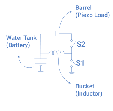
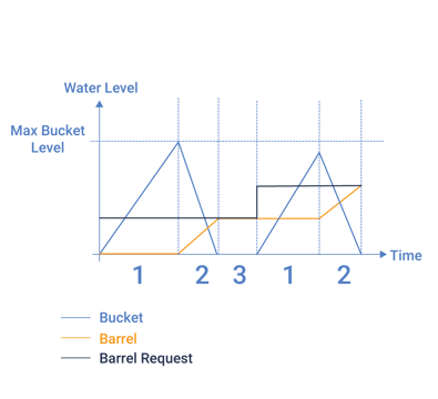
- Fill the bucket from the tank (S1 closed, S2 opened)
- Empty the bucket in the barrel (S1 open, S2 closed)
- Wait for request from the barrel (S1 opened, S2 opened)
*Repeat as needed
The electrical detail
The power transfer can be approximated as follows. The energy the inductor can shuttle in a single cycle is set by its inductance L and the current I that flows in it.
E = ½ · L · I²
The charge and discharge times are approximated by:
t = L · I / V
where V is the voltage across the inductor. When charging the inductor, the voltage is the supply, and when discharging, the voltage is the load voltage.
Combining the energy per cycle with the total transfer time gives the average output power:
P = E / (t_cycle)
Frequently asked questions
Is CapDrive a buck or a boost converter?
It is both — a buck and a boost converter with self-managed behavior. The controller switches between modes automatically, cycle by cycle, rather than being fixed as a step-up or step-down, which is how it tracks an arbitrary output efficiently.
What kind of loads can CapDrive work with?
Any capacitive loads such as piezo actuators, MEMS and capacitors, from the low-nanofarad range up to a couple of microfarads. Each Boréas IC specifies a recommended load impedance range for its target applications.
What output voltages and waveforms can CapDrive produce?
Boréas ICs can produce any arbitrary waveform up to 120 V, unipolar or bipolar, AC or DC, depending on the selected product.
When driving a load, smooth waveforms such as sine waves or Gaussians are recommended to minimize audible noise — see Boréas's app note on audible noise reduction.
How does CapDrive save energy?
It works as a bidirectional energy pump: rather than dumping the load's stored energy as heat, it recovers that energy back to the power rail. The power consumed is therefore only losses in the actuator load, and from the conversion process.
What are the main sources of power loss?
The main losses are due to the inductor's resistance (DCR) and magnetic core, the transistor channel, and gate-drive switching. All are small relative to the energy delivered.
What external components does CapDrive require?
Key external passives required are a power inductor, a sensing resistor and low-cost capacitors. Some products also require external FETs.
What sets the maximum output power?
The absolute maximal output power is set by each product based on design and target applications. Then, the BOM can be set to define a maximum power transfer suited to a specific application. This can be done using Boreas' BOM calculator to optimize the BOM and reduce the solution footprint.
Glossary
Piezoelectric actuator: an electro-mechanical transducer component that physically expands or contracts when a voltage is applied, used here to create motion the user feels as a “click” or to displace fluid in microfluidics applications. It can also sense mechanical deformation to create a voltage differential, used to track force application.
Haptic driver: The circuit that generates and shapes the electrical signal sent to an actuator to produce a specific tactile effect.
LRA (Linear Resonant Actuator): A common vibration motor that oscillates a mass at a fixed resonant frequency to produce buzz-like feedback.
HD haptics: Sharp, fast-rising tactile effects with distinct edges, as opposed to the diffuse "buzz" of resonant motors.
Related reading
-
BOS1211 high-voltage piezo driver for automotive applications
-
How piezo microfluidic cooling uses a CapDrive driver (BOS1931)
Next steps
Evaluate CapDrive® with a development kit → https://www.boreas.ca/collections/development-kits
Discuss your haptic design with our applications engineering team → info@boreas.ca
Explore the CapDrive® technology overview and product documentation → https://www.boreas.ca/pages/capdrive-technology
About the author
Frederick Leclerc, [Hardware Designer] — Boréas Technologies.
Leave a comment